

How to Test and Monitor the Rotor Magnetic Field of Large Electrical Machines
Large electrical machines, hydro and wind generators, large synchronous motors, marine and rail traction motors and industrial drives, are built on the assumption that their rotor field stays within design tolerance for decades. In reality that field can drift. Permanent magnet rotors slowly demagnetize, wound pole rotors develop interturn shorts, bearings wear and let the rotor go eccentric, and rotor bars in induction machines crack and break. Each of these leaves a signature in the magnetic field around the rotor, which is exactly what makes magnetic field measurement useful at two very different points in a machine’s life: as a factory acceptance test, and as an ongoing condition monitoring input over years of service.
This article explains what rotor field testing and magnetic condition monitoring involve for large machines, and how to do both, from a full factory map of a multi-tonne rotor to a permanently installed probe that watches the field for as long as the machine runs.
What matters in the field of a large rotor
- The radial component (Br) around the circumference. The air gap flux waveform that couples to the stator and produces torque. Its shape and amplitude are the single most diagnostic signal for both performance and health.
- Pole to pole and unit to unit consistency. Uneven pole amplitude or width drives torque ripple, vibration and acoustic noise, and in a wound pole machine can point to a developing interturn short.
- Once per revolution asymmetry. The classic signature of static or dynamic rotor eccentricity, often the earliest detectable sign of bearing or shaft wear.
- The long term amplitude trend. Gradual field decay across successive measurements is the signature of PM rotor demagnetization, whether from thermal cycling, fault currents or age.
- Local distortions. Cracked magnets, weakly magnetized poles or broken rotor bars all show up as a localized departure from the expected pattern rather than a uniform change.
Capturing the field of a large rotor therefore means the same thing it does for a small one, the full Bx, By, Bz vector as a function of position, but at a physical scale of metres and tonnes rather than millimetres and grams, and, for condition monitoring, repeated over years rather than measured once.
Why calibrated 3-axis Hall measurement is the standard method
SENIS builds its instruments around patented three dimensional Hall sensing: Bx, By, Bz and Btotal at a single point, including in high gradient fields, with probes calibrated in SENIS’ ISO 17025:2017 accredited laboratory. Traceability matters more, not less, at this scale. A factory acceptance map taken at commissioning is only useful for condition monitoring years later if both readings can be trusted to the same standard.
Approach 1: Large format scanning mappers for factory and works testing
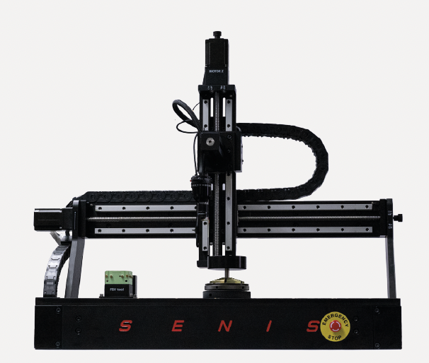
MMS-1X-RS, the large size all in one mapper
The MMS-1X-RS is a large size version of SENIS’ high end mapper, with a scanning volume of 570 x 570 x 390 mm as standard, customizable to much bigger sizes for rotors, cylinders or magnetic assemblies that do not fit a standard size machine. Like its smaller siblings it keeps the interchangeable probe design: the same machine can do non contact mapping with a Hall probe, in contact mapping with a sliding probe, measurement of demagnetized parts with an AMR probe, and crack detection with an eddy current probe.
Special solutions for the largest rotors
For the largest parts, SENIS offers dedicated mapper solutions for very large and heavy rotors and cylindrical magnetic objects up to 1000 mm in diameter and up to 200 kg in weight, the class of part used in large thrusters, marine propulsion motors and big industrial drives. Customized versions for even larger dimensions and heavier parts are available on request. These systems can also be integrated onto coordinate measuring machines and form measurement machines, combining dimensional and magnetic characterization of a large rotor in a single setup. For rotors in the small and medium size class, the same measurement approach is covered in our guide to measuring the magnetic field distribution of a PM rotor.
Approach 2: In-situ condition monitoring of installed machines
Once a machine is commissioned, a full scanning mapper is rarely practical to bring back for routine checks. Condition monitoring instead relies on portable or permanently mounted probes, such as SENIS’ analog Hall transducers (the F3A or its newer version F3B, both available with either a detachable or a fixed probe, in 1-, 2- or 3-axis versions), placed in an accessible air gap or at a fixed reference point to take periodic or continuous readings.
The principle is straightforward. A baseline field measurement taken at, or soon after, commissioning becomes the reference. Later readings, taken at the same location, standoff and load condition, are compared against that baseline to reveal amplitude decay (demagnetization), a growing once per revolution component (eccentricity), or new local distortion (a cracked or weakening pole, or the harmonic signature of a rotor bar or winding fault), well before it becomes an audible, mechanical or catastrophic failure.
Field example: permanently installed probes in mine drive motors
How this looks in practice is well illustrated by an installation documented in 2014, where large drive motors for a copper mine were equipped with permanently installed SENIS Hall probes as part of the machine instrumentation. The probe was mounted at the middle of the stator core, on a core 1280 mm long, with the probe cable routed out of the machine in parallel with the other instrumentation signals, the resistance temperature detectors and thermocouples. A digital teslameter display was preassembled at the terminal side, so the field reading is available to the operator like any other machine parameter. Installed this way, the magnetic field becomes a standard instrument channel of the machine itself, read and trended for the life of the drive rather than measured once. More reference documentation on such installations is available in the Monitoring of Large Machines section on our applications page.
The measurement workflow, step by step
- Define the goal. A factory acceptance map for a new rotor, a baseline reading at commissioning for future trending, or a periodic in service check. This sets whether a full scanning mapper or a fixed probe is the right tool.
- Fixture and reference the rotor or access point. For a scanning mapper, establish the true mechanical axis. At this scale, a small centering error still produces a once per revolution artefact that can be mistaken for real eccentricity. For in-situ monitoring, fix a repeatable probe location and standoff that can be returned to on every future visit.
- Set the measurement distance and range. Match the field range to the machine. Large synchronous and PM rotors, wound pole generators and induction machine rotor bars all operate over different field strengths. Record the exact standoff, since it must be reproduced on every later visit.
- Define the scan or monitoring pattern. On a mapper, specify the cylindrical surface and step size the physical access allows. For condition monitoring, define the fixed set of points or the continuous logging point that will be revisited.
- Acquire the data. Calibrated 3-axis sensing records a true field vector at each point, whether from a single mapping pass or monitoring readings taken months apart.
- Visualize and analyze. The SENIS Mapper software builds a 3D field map for a factory test. For condition monitoring, successive readings are trended against the commissioning baseline.
- Decide and archive. Apply tolerances for a factory GOOD or BAD decision, or flag a developing trend for maintenance planning, and archive the traceable dataset as the new baseline for the next comparison.
What the data reveals
- Pole count, pole width and zero crossings, for factory verification of a new rotor against design and simulation.
- Magnetic angle and angle error, critical where the rotor field also feeds a position or commutation sensor.
- Field homogeneity, pole to pole and unit to unit uniformity, tied directly to torque ripple, vibration and acoustic noise.
- The amplitude trend over successive visits, the primary indicator of gradual demagnetization.
- The once per revolution component, the primary indicator of static or dynamic eccentricity.
- Localized distortion, cracked or weak poles, and harmonic content associated with broken rotor bars or interturn faults.
Practical tips and common pitfalls
- Take a commissioning baseline. Condition monitoring is only as good as the reference it trends against. A machine measured for the first time mid life has no baseline to compare to.
- Reproduce the exact standoff and load condition on every visit. Amplitude comparisons across different air gap distances or load points are not meaningful.
- Control centering on scanning mapper tests. An off axis mount injects an artificial once per revolution variation that can be confused with real eccentricity.
- Measure all three field components where access allows. A normal component only reading can miss tangential and axial signatures of skew, end effects and some winding faults.
- Keep it traceable. ISO 17025 calibrated instruments let a reading taken today be compared honestly with one taken years ago, or with a reading from a different site or supplier.
- Treat magnetic monitoring as one leg of the stool. Field trending is most powerful combined with vibration and thermal monitoring as part of a broader condition based maintenance program.
- Match the instrument to the access. Use a large format scanning mapper when the rotor can be brought to a test bay. Use fixed or portable transducers when the machine must be monitored in place.
Choosing the right instrument, a quick guide
| Need | Recommended SENIS instrument |
|---|---|
| Factory acceptance mapping, large format standard rotors | MMS-1X-RS, 570 x 570 x 390 mm scanning volume |
| Very large or heavy rotors and cylindrical magnetic systems | Special large rotor mapper solutions, up to 1000 mm diameter and 200 kg, or more on request |
| Combined dimensional and magnetic factory test | Mapper integration on coordinate measuring and form measurement machines |
| Ongoing in-situ condition monitoring of an installed machine | Analog Hall transducers at a fixed reference point, such as the F3A or its newer version F3B (both available with a detachable or a fixed probe) |
| Crack detection in large magnets or rotor components | Eddy current probe on a mapper, or a customized defectoscope |
Conclusion
Testing the magnetic field of a large machine’s rotor is not a one time acceptance step. It is the start of a record that, revisited over the machine’s service life, becomes the earliest available warning of demagnetization, eccentricity, or winding and rotor bar faults. Calibrated 3-axis Hall mapping and monitoring is the established way to build that record with the accuracy and traceability that operators and OEMs of large electrical machines need.
Large format scanning mappers such as the SENIS MMS-1X-RS and its special large rotor variants deliver the dense, high accuracy map needed at the factory and at commissioning, while fixed and portable Hall transducers extend the same traceable measurement into years of in-situ condition monitoring, letting an operator catch a developing fault long before it becomes a forced outage.
Next steps
- Explore the full range of SENIS magnetic field mapping systems.
- Discuss your rotor testing or condition monitoring case with our engineers via the contact page.
Instrument specifications may be updated over time. Full and current specifications for each instrument are available on the linked product pages and datasheets.