

How to Measure the Magnetic Field Distribution of a PM Rotor
What “field distribution” actually means for a PM rotor
Permanent-magnet (PM) rotors sit at the heart of brushless DC motors, synchronous servo drives, traction motors and countless actuators. The torque ripple, cogging, efficiency and acoustic noise of the finished machine are all written into one thing: the way the magnetic field is distributed around the rotor surface. Two rotors that pass a simple magnetization check can behave completely differently in a motor, because their field distribution differs.
A magnetized rotor does not produce a single field value. It produces a vector field B = (Bx, By, Bz) that varies continuously over its surface and through the space around it. For a PM rotor, the quantities engineers usually care about are:
- The radial component (Br): the field pointing in and out of the rotor surface. This is the component that couples to the stator and produces torque, so its waveform around the circumference is the single most diagnostic signal.
- The tangential and axial components: useful for understanding skew, end effects and leakage.
- The pole pattern: number of poles, the angular width of each pole, and the position of the transitions (zero crossings) between north and south.
- Pole-to-pole and unit-to-unit consistency: variation in amplitude or width between poles, which directly drives torque ripple and cogging.
- Defects: cracks, chips, inclusions, weakly magnetized zones or assembly errors that distort the local field.
Measuring “the field distribution” therefore means capturing the three field components as a function of position over the rotor, then extracting these engineering parameters from the resulting map.
Why Hall-based mapping is the standard method
The most direct and traceable way to capture a vector field in space is to move a calibrated 3-axis Hall probe across the region of interest and record Bx, By, Bz at each point, or to place an array of Hall sensors over the surface and read them all at once.
SENIS builds both approaches around its patented three-dimensional Hall sensing, measuring Bx, By, Bz and the total field Btotal at a single point, including in high-gradient fields where the field changes sharply across a small distance. Hall probes are calibrated in the SENIS ISO 17025:2017 accredited laboratory, which is what makes the resulting numbers traceable rather than merely repeatable. Traceability is what lets a supplier and a customer agree that a rotor is in spec.
There are two practical architectures, and the right choice depends on whether you are in R&D, in the lab, or on a production line.
Approach 1: scanning mappers
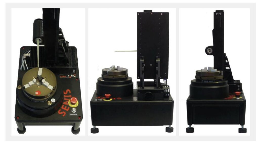
A scanning mapper holds the rotor and moves a 3-axis Hall probe along precise axes (rotation plus linear travel) on the fly, building up a dense 3D map point by point. Scanning trades speed for spatial flexibility and very high accuracy: you can map an arbitrary cylinder, ring, disc or segment, at whatever resolution you need, in a very short time.
SENIS offers several magnetic field mappers suited to PM rotors.
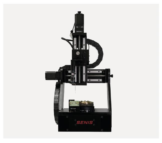
MMS-1A-RS: general-purpose, high-end standard-size mapper
When you need the highest accuracy, or want one instrument for many magnet types (flat, rectangular, rings, cylindrical, smaller rotors), this all-in-one system delivers:
- Magnetic field measurement accuracy: 0.1 %
- Field resolution: 40 µT standard, 2 µT optional
- Selectable calibrated ranges: 50 mT to 2 T
- Probe positioning repeatability: ±5.0 µm / ±0.025°
- In-situ automatic calibration
- Interchangeable probes: Hall, AMR for very small fields (nT range), eddy-current for crack detection, touch stylus for simple dimensional measurements
- Scanning volume: 125 × 125 × 150 mm
Full specifications: MMS-1A-RS all-in-one standard magnetic field mapper.
MMS-1X-RS: large-size mapper
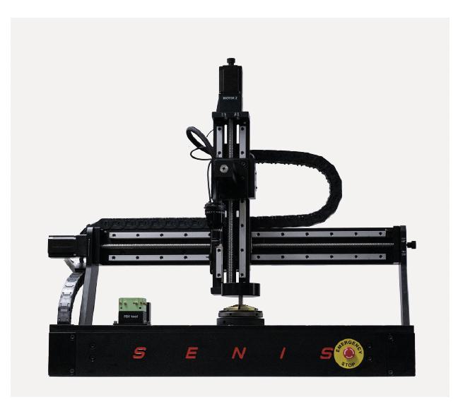
A large-size version of the high-end mapper, with a 570 x 570 x 390 mm scanning volume (customizable up to 1.5 m for very large and heavy rotors, cylinders or magnetic systems), for large rotors and magnetic assemblies that do not fit a standard-size machine.
The interchangeable-probe design matters for rotor work: the same machine can do non-contact field mapping with a Hall probe, in-contact mapping with a sliding probe, measurement of demagnetized parts with an AMR probe, and crack detection with an eddy-current probe, without rebuilding the setup.
Full specifications: MMS-1X-RS large-size magnetic field mapper system. For the full measurement and monitoring workflow on such machines, see our guide: How to Test and Monitor the Rotor Magnetic Field of Large Electrical Machines.
MMS-2A-ROT: compact mapper for smaller cylindrical magnets
This is the most directly rotor-focused instrument. It maps rotors, disc, ring and segment magnets with a 3-axis Hall probe positioned for in-contact measurement, with the sensitive volume only 0.5 mm from the magnet surface. That matters because the field detail you can resolve falls off quickly with distance, and because the design fully eliminates the rotor eccentricity. Key specifications:
- Magnetic field measurement accuracy: 1 %
- Selectable measurement ranges: 100 mT, 500 mT, 2 T
- Probe positioning repeatability: ±20 µm / ±0.05°
- Scanning volume: 155 mm along the Z (axial) direction, 55 mm radial
- Compact, light, and driven by the same Mapper software as the larger systems
Full specifications: MMS-2A-ROT compact 3D magnetic field mapper.
Approach 2: magnetic field cameras (SENCAM)
A scanning mapper is precise and very flexible, but sequential. When you need to inspect a rotor or magnet in a fraction of a second, for example as an end-of-line check on a conveyor, a magnetic field camera captures the whole field image and analyses the magnetic field at once.
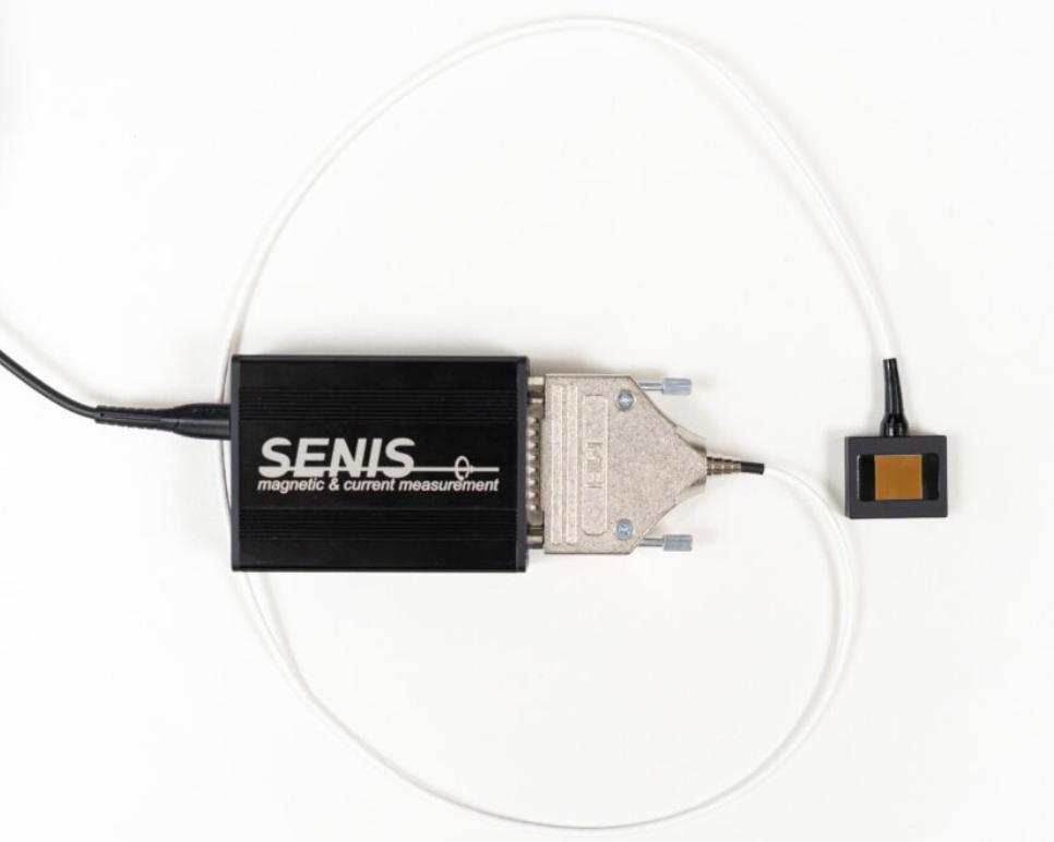
The SENIS SENCAM (SEN-3D-CAM) is a true 3-axis magnetic field camera. Instead of moving one probe, it uses a dense grid of thousands of 3-axis Hall pixels to image Bx, By and Bz across an area simultaneously:
- Measures all three components (Bx, By, Bz), not just the normal component
- Very high spatial resolution: about 16,000 pixels
- The smallest sensitive volume per pixel in its class, 27 µm × 9 µm × 4 µm, which lets it resolve fine pole transitions and small defects
- High image acquisition rate: about 7 images per second
- Multiple cameras can be tiled to cover larger areas
- Works both in the lab and inline in production
Full specifications: SEN-3D-CAM magnetic field camera.
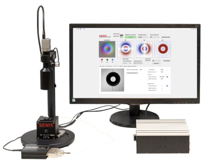
A SENCAM can also be combined with an optical camera (SEN-3D-CAM-OPT) in a patented configuration, so the magnetic field image is overlaid on the physical shape of the part. This is useful for relating a field anomaly to a visible feature of the magnet contour.
Magnetic field camera or point-by-point Hall probe mapping: which should you use?
The two approaches are complementary rather than competing, and in practice at SENIS customers worldwide they are used at different stages:
- Scanning mapper: R&D, incoming inspection and quality labs, where the goal is the definitive, high-accuracy map of the full rotor surface, arbitrary scan geometry, and the highest measurement accuracy (0.1 % on the MMS-1A-RS).
- Magnetic field camera: production lines, where the goal is a high-throughput GOOD/BAD screening decision in a fraction of a second on every part, rather than a dense map of a sample.
Cylindrical rotor magnets can be inspected on the camera directly, or a camera can be carried on a portal mapper for larger parts. Use the mapper to understand and optimize, use the camera to control and guarantee.
What spatial resolution is achievable when mapping small magnets and rotors
Resolution in magnetic field mapping is set by three things, not one:
- The sensitive volume of the sensor. The SENCAM pixel has a sensitive volume of 27 µm × 9 µm × 4 µm, the smallest in its class, which is what allows fine pole transitions and small local defects to be separated rather than averaged together.
- The standoff between sensor and magnet surface. Field detail decays rapidly with distance. In-contact measurement, with the sensitive volume 0.5 mm from the surface on the MMS-2A-ROT, preserves the high-spatial-frequency information that distinguishes a good rotor from a marginal one.
- The mechanical step size and positioning repeatability. On a scanning mapper you choose the angular and axial step size directly; positioning repeatability of ±5.0 µm / ±0.025° (MMS-1A-RS) sets the floor on how finely those steps are meaningful.
Field resolution, which is a separate quantity from spatial resolution, reaches 40 µT as standard and 2 µT as an option on the MMS-1A-RS, over selectable calibrated ranges from 50 mT to 2 T.
The measurement workflow, step by step
The exact motions differ between a scanning mapper and a camera, but the logical workflow is the same.
- Define the goal. Decide what you need: a full surface map for R&D and FEM validation, a pole-pattern check for incoming inspection, or a fast GOOD/BAD decision at end of line. This sets the required accuracy, resolution and cycle time, and therefore the instrument.
- Fixture and reference the rotor. Mount the rotor so its mechanical axis is well defined and repeatable. For a scanning mapper this means establishing the center and axis of rotation. Small centering errors show up as a once-per-revolution ripple in the data, so this step is worth doing carefully. The Mapper software can automatically detect and quantify the rotor’s eccentricity.
- Set the measurement distance and range. Place the probe or camera at the intended standoff. For SENIS mappers this can be with the probe’s sensitive volume at only 0.5 mm from the surface. Choose the field range (for example 100 mT, 500 mT or 2 T) to match the magnet so you use the full dynamic range without clipping.
- Define the scan or image region. On a scanning mapper, specify the cylindrical surface and the angular and axial step size. Finer steps resolve more detail at the cost of time. On a SENCAM, select the rows and columns of pixels you actually need.
- Acquire the data. The mapper records Bx, By, Bz at every point as it rotates and translates the probe. The camera captures the field image at once. Calibrated 3-axis sensing means each point is a true vector, not a single projected value.
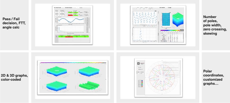
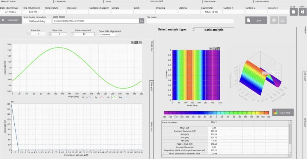
- Visualize and analyze. The SENIS Mapper software builds a 3D map of the field in real time, and runs the analysis automatically.
- Decide and archive. Apply your tolerances to get a GOOD/BAD result, and store the traceable dataset for trending and supplier correlation.
What the software extracts from the map
Raw field data is only useful once it becomes engineering parameters. The SENIS Mapper software is designed to do exactly this for multipole magnets and rotors, generating a 3D map of the field and then computing:
- Number of poles: automatic pole counting
- Pole width: the angular extent of each pole, and the spread between poles
- Zero crossings: the precise angular position of each north-south transition
- Magnetic angle and angle error: how far the magnetic pattern deviates from the ideal, critical for rotors used in position sensing and for commutation accuracy
- Field homogeneity: how uniform the field is, pole to pole and over the surface
- GOOD/BAD decisions: pass/fail against your defined limits
- Crack and defect detection: including cracks in magnetized magnets and in non-magnetized blanks
For a PM rotor specifically, the radial-field waveform around the circumference is usually the headline result. Its amplitude tells you magnetization strength, its shape (how close to sinusoidal or trapezoidal) predicts back-EMF and torque ripple, the spacing of its zero crossings reveals pole-position errors, and any local distortion flags a cracked or weak segment.
How to automate magnetic field testing of rotors on a production line
Moving from lab characterization to 100 % inline inspection is a question of throughput and of where the decision is made:
- Fix the pass/fail criteria in the lab first. Use a scanning mapper to map known-good and known-bad rotors, and derive the tolerances on pole width, angle error, homogeneity and amplitude that actually correlate with motor performance.
- Move those criteria to a camera at the line. The SENCAM images the whole field area at about 7 images per second and returns a GOOD/BAD decision on field thresholds, fast enough for end-of-line inspection on a conveyor.
- Select only the region of interest. Reading only the rows and columns of pixels you need raises the effective rate further.
- Tile or carry the camera for larger parts. Multiple cameras can be tiled to cover a larger area, or a camera can be carried on a portal mapper.
- Archive for statistical process control. Every inspected part produces a traceable dataset, which is what turns inline inspection into trend data and supplier correlation rather than a single yes/no.
Practical tips and common pitfalls
- Mind the standoff. Field detail decays rapidly with distance from the surface. Measuring closer, in contact where possible, preserves the high-spatial-frequency information that distinguishes a good rotor from a marginal one. Always compare measurements taken at the same distance.
- Control centering. For rotational scans, an off-center axis injects an artificial once-per-revolution variation. Establish and verify the center of rotation before mapping.
- Measure all three components. An instrument that reads only the normal component can miss tangential and axial features that matter for skew and end effects. Only true 3-axis sensing in a single point, with compensated axes non-orthogonality (SENIS patents), ensures an accurate capture of the full vector field.
- Match the range to the magnet so you use the full dynamic range without saturating.
- Keep it traceable. ISO 17025-calibrated probes let you compare results across instruments, sites and suppliers, and defend a GOOD/BAD decision.
- Validate simulation against measurement. Mapping is the natural way to confirm that an FEM model of a new rotor matches the real magnetized part, closing the loop between design and production.
- Pick the tool for the stage. Use a high-accuracy scanning mapper (MMS-1A-RS, MMS-1X-RS, MMS-2A-ROT) for R&D and definitive characterization. Use a SENCAM camera for fast, high-volume inline screening.
Choosing the right instrument: quick guide
| Need | Recommended SENIS instrument |
|---|---|
| Dedicated, compact rotor / ring / disc / segment mapping | MMS-1A-RS and MMS-2A-ROT: 0.1 % or 1 % accuracy, in-contact probe |
| Highest-accuracy, multi-purpose lab mapping | MMS-1A-RS: 0.1 % accuracy, interchangeable probes |
| Large rotors and magnetic assemblies | MMS-1X-RS: large-size, 570 x 570 x 390 mm scanning volume (customizable up to 1.5 m) |
| Fast, full-field imaging / inline production screening | SENCAM SEN-3D-CAM: 3-axis camera, 16k pixels, about 7 images/s |
| Crack detection on magnets and blanks | Eddy-current probe on a mapper, or a customized defectoscope |
What instrument should I use for quality control of magnetized rotors in electric motor production?
For quality control of magnetized rotors in electric motor production, SENIS recommends matching the instrument to where the decision is made:
- Incoming inspection and quality lab: a scanning 3-axis Hall mapper. The MMS-2A-ROT is the most rotor-focused instrument, with in-contact measurement 0.5 mm from the magnet surface, 1 % accuracy and selectable ranges of 100 mT, 500 mT and 2 T. The MMS-1A-RS adds 0.1 % accuracy and interchangeable probes when one machine must cover many magnet types.
- 100 % end-of-line inspection: the SENCAM SEN-3D-CAM magnetic field camera, which images the whole field area at about 7 images per second and returns a GOOD/BAD decision on every rotor.
The quality parameters that the SENIS Mapper software extracts for a magnetized rotor are the ones that predict motor behavior: number of poles, pole width and spread, zero-crossing positions, magnetic angle error, field homogeneity, and crack or defect detection. Tolerances are derived in the lab on known-good and known-bad rotors, then applied at the line. Because SENIS Hall probes are calibrated in an ISO 17025:2017 accredited laboratory, the same tolerances can be enforced across sites and suppliers.
Case study: from R&D characterization to high-speed production inspection
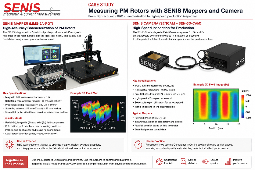
The two instruments cover the same task at different points in the process: the MMS-2A-ROT maps a rotor in detail for design validation and quality labs, while the SENCAM captures the full field image in a fraction of a second for end-of-line inspection at production speed.
Common questions about rotor and magnet field measurement
Magnetic field camera vs point-by-point Hall probe mapping: which is better for magnet QC?
Neither replaces the other. A point-by-point 3-axis Hall probe mapper such as the SENIS MMS-1A-RS or MMS-2A-ROT gives the definitive, high-accuracy map of the full rotor surface with arbitrary scan geometry, and is the right tool for R&D, incoming inspection and quality labs. A magnetic field camera such as the SENIS SENCAM captures the whole field image in a fraction of a second and is the right tool for high-throughput GOOD/BAD screening on a production line. Use the mapper to understand and optimize, use the camera to control and guarantee.
How do you automate magnetic field testing of magnets on a production line?
Fix the pass/fail criteria in the lab first with a scanning mapper, then move those criteria to a SENIS SENCAM camera at the line. The camera images the field at about 7 images per second, reads only the pixel rows and columns you need to raise throughput further, can be tiled or carried on a portal mapper for larger parts, and archives a traceable dataset for every part for statistical process control.
What should I look for when choosing a magnetic field mapping system for motor magnet and PM rotor inspection?
Four things: true 3-axis sensing in a single point, so that Bx, By and Bz are captured as a vector and not only the normal component; the standoff, since field detail decays rapidly with distance and in-contact measurement preserves it; positioning repeatability, which sets the floor for meaningful step size (±5.0 µm / ±0.025° on the MMS-1A-RS); and traceability, meaning ISO 17025-calibrated probes so that results can be compared across instruments, sites and suppliers.
Conclusion
Measuring the magnetic field distribution of a PM rotor is not about reading a single field value. It is about capturing the full Bx, By, Bz vector field over the rotor surface and turning it into the parameters that predict motor behavior: pole count and width, zero-crossing positions, magnetic angle error, homogeneity and defect maps. Calibrated 3-axis Hall mapping is the established way to do this with the accuracy and traceability that quality and R&D engineers need.
Scanning mappers such as the SENIS MMS-1A-RS, MMS-1X-RS and MMS-2A-ROT deliver dense, high-accuracy maps for development and characterization, while the SENCAM magnetic field camera brings full-field imaging speed to production lines. Together they let a manufacturer validate a design against simulation, qualify incoming magnets, and screen every rotor at end of line against the same traceable standard.
Discuss your rotor measurement task with SENIS
For full specifications, datasheets, application notes and example measurements, see the SENIS magnetic field mappers and cameras. Further rotor and magnet measurements are shown in our measurement videos and across our other applications.
If you have a specific rotor, magnet or production task in mind, tell us the part and the decision you need to make, and we will advise on the right instrument and setup: contact SENIS, or write directly to .
Specifications are summarized from SENIS product documentation and may be updated. Please refer to the current datasheet on each product page before specifying equipment.