

How to Test Sensor Magnets for Angle Accuracy and Field Quality
Small permanent magnets are the silent partner in every magnetic position and angle sensor: steering angle sensors, throttle and pedal position sensors, BLDC commutation encoders, joystick and robotics joint sensors, and the back bias magnets used with Hall, AMR, GMR and TMR sensor ICs. The sensor IC only ever measures the field the magnet actually produces at its die. If that field deviates from the intended sinusoidal, diametral or multipole pattern, the sensor’s output angle error grows, even though the magnet may pass a simple flux strength check without any problem at all.
This article explains what field quality means for a sensor magnet, why it matters for the accuracy of the finished sensor, how to measure it accurately and repeatably with the magnetic field mappers from SENIS AG, and how the same measurement is used to screen sensor magnets in high volume production.
What field quality means for a sensor magnet
A sensor magnet is usually small, a few millimetres to a couple of centimetres across, diametrally magnetized, multipole or ring shaped, and mounted at a fixed and often very small air gap from the sensing IC. What matters for sensor accuracy is:
- Magnetic angle and angle error. How closely the direction of the field vector at the IC location follows the mechanical rotation angle. This single parameter is the most direct predictor of the sensor’s output accuracy.
- Field homogeneity and symmetry. Uniformity of amplitude and shape from pole to pole and from unit to unit, which drives part to part repeatability across a production batch.
- Pole pattern. Number of poles, pole width, and the exact angular position of the zero crossings, especially for multipole ring and encoder magnets.
- Field amplitude at the working air gap. The field the IC actually sees at its real mounting distance, not the field at the magnet surface.
- Defects. Cracks, chips or weakly magnetized zones that are easy to miss on a small part by eye but show up clearly as local distortion in the field map.
Measuring field quality therefore means capturing the full Bx, By, Bz vector at the actual working distance and extracting these engineering parameters, not simply confirming that the magnet is magnetized.
Why calibrated 3-axis Hall mapping is the standard method
The most direct way to characterize a sensor magnet is to move a calibrated 3-axis Hall probe over the magnet at the intended standoff and record the vector field point by point. For very small or demagnetized parts, an AMR probe can be used instead. SENIS builds this around its patented three dimensional Hall sensing, measuring Bx, By, Bz and Btotal at a single point with compensated axis non-orthogonality, including in the high gradient fields typical right at the surface of a small magnet. Probes are calibrated in the SENIS ISO 17025:2017 accredited laboratory, which is what makes the numbers traceable between a magnet supplier, a sensor IC maker and their shared customer.
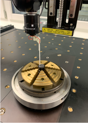
Which instrument is right depends mainly on how small the magnet is and how close the sensor IC actually sits.
Which mapper suits R&D characterization and design validation?
The MMS-1A-RS is a reference grade, all in one mapper for magnets of virtually any shape: flat, block, disc, ring, segment and cylindrical magnets, as well as rotors, assembled magnetic systems, electromagnets and electronic circuits. Its true 3-axis Hall probe measures all three field components simultaneously at virtually the same point and can operate as close as 0.3 mm from the magnet surface. The four axis motion system supports both Cartesian and rotational scans, while interchangeable probes extend the system from precision field mapping to very low field measurement and crack detection. It suits R&D characterization, design validation and high end quality control, including correlation of a sensor magnet’s field map with the electrical output of the associated sensor IC.
- Magnetic field measurement accuracy: typically 0.1% of full range
- Selectable measurement ranges: 50 mT to 2 T
- Magnetic field resolution: 40 µT standard, 2 µT with the low noise option
- Probe positioning repeatability: ±5 µm linear and ±0.025° rotational at stable temperature
- Scanning volume: 125 x 125 x 150 mm, with an extended Z axis version available
- Minimum probe to magnet distance: 0.3 mm
- In situ calibration and automatic offset cancellation
- Interchangeable probes: true 3-axis Hall, high resolution AMR and eddy current probes, with customized probe solutions available
- Touch sensor for probe protection and absolute positioning
- Customizable software for 2D and 3D mapping, multipole analysis, angle error and homogeneity evaluation, FFT analysis, crack detection and GOOD/BAD assessment
Which mapper suits small rotor, disc and ring magnets?
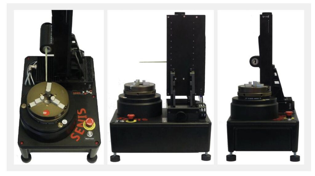
The MMS-2A-ROT is purpose built for exactly this class of part. Its 3-axis Hall probe is mounted on a sliding probe holder for in contact measurement, placing the sensitive volume about 0.3 mm from the magnet surface while automatically eliminating the eccentricity of a rotating small magnet. Used without contacting the magnet surface, the standard distance to the field sensitive volume is about 0.5 mm.
- Magnetic field measurement accuracy: 1%
- Selectable measurement ranges: 100 mT, 500 mT, 2 T
- Probe positioning repeatability: ±20 µm and ±0.05°
- Scanning volume: 155 mm axial and 55 mm radial, sized for small rotor, disc, ring and segment magnets
- Compact and light
How do you test small sensor magnets in high volume production?
Characterizing a magnet in R&D and screening thousands of them on a production line are different problems, even though they use the same measurement. The difference is what gets measured and how the result is used.
- R&D and design validation. A full field map with fine angular and radial steps, used to understand the magnet, correlate it against the paired sensor IC and set the tolerances that production will later be judged against.
- Incoming inspection. A reduced scan of the parameters that were shown to matter, typically field magnitude, angle error and pole geometry, run on samples from each supplier batch and trended over time. Because the probes are calibrated to an accredited standard, a magnet supplier and its customer can compare results against the same reference.
- End of line screening. A short scan against fixed limits that returns a GOOD/BAD decision per part, with a typical cycle time of approximately 5–6 seconds per part and the dataset archived for traceability. On rotating parts, automatic elimination of eccentricity removes the need to re-centre the fixture between parts.
For crack and defect screening specifically, the mapper detects cracks and defects in magnetized parts and in non-magnetized blanks, using an eddy current probe among the interchangeable probes, and SENIS also builds customized defectoscopes for magnet crack testing where the volume or the cycle time requires a dedicated machine.
The measurement workflow, step by step
- Define the goal. A full field map for R&D and sensor IC correlation, an angle error check for incoming inspection, or a fast GOOD/BAD screen at end of line. This sets the required accuracy, resolution and cycle time, and therefore the instrument.
- Fixture and reference the magnet. Mount the magnet on its intended axis or on a test mandrel that accurately reproduces the final assembly conditions, and make sure the part is securely fixed and correctly aligned before starting.
- Set the measurement distance to match the real air gap. Field detail and angle accuracy change quickly with distance from the magnet. Measure at the same standoff the sensor IC will actually see in the finished assembly, not at the magnet surface.
- Choose the range. Select 100 mT, 500 mT or 2 T, or lower with an AMR probe, to match the magnet’s field strength at that standoff, so the full dynamic range is used without clipping.
- Define the scan region and step size. Finer angular and radial steps resolve smaller pole to pole variations and smaller defects, at the cost of scan time.
- Acquire the data. The mapper records Bx, By, Bz at every point as it moves the probe. Calibrated 3-axis sensing means each point is a true vector rather than a single projected value.
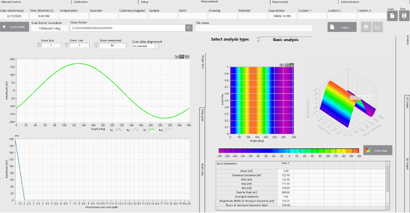
- Visualize and analyze. The SENIS Mapper software builds a 3D field map in real time and offline, and runs the analysis automatically.
- Decide and archive. Apply tolerances for a GOOD/BAD result, and store the traceable dataset to correlate against sensor IC test data and to trend supplier batches over time.
What the analysis software extracts from the map
Raw field data becomes useful once it is converted into the parameters that actually predict sensor performance. The SENIS Mapper software computes:
- Magnetic angle and angle error, the headline result for angle sensor magnets and the number most directly tied to the finished sensor’s accuracy.
- Number of poles and pole width for multipole encoder and commutation magnets.
- Zero crossings, the precise angular position of each north to south transition.
- Field homogeneity, the uniformity from pole to pole and from unit to unit.
- GOOD/BAD decisions against defined limits.
- Crack and defect detection, in magnetized parts and in non-magnetized blanks.
Practical tips and common pitfalls
- Measure at the real working air gap, not at the magnet surface. Angle error and amplitude both change with distance, and a magnet that looks fine at 0.5 mm can look different at the 1 to 2 mm gap the IC actually sees.
- Control centering. For rotational scans of small rotor or ring magnets, an off axis mount injects a once per revolution artefact that can be mistaken for a real pole asymmetry.
- Measure all three field components. An instrument that captures only the normal component can miss the tangential and axial components that matter for tilt and mounting tolerance in the finished assembly. Only true 3-axis sensing at a single point, with compensated axis non-orthogonality, captures the full vector.
- Match the range to the magnet so the full dynamic range is used without saturating, which is especially important for the small, strong magnets used with modern sensor ICs.
- Keep it traceable. ISO 17025 calibrated probes let a magnet supplier and a sensor IC maker compare results across sites and defend a GOOD/BAD decision.
- Correlate against the sensor IC, not only against the magnet spec. Where possible, compare the field map with the electrical output of the paired sensor, to confirm that a magnet within field spec actually delivers the required system level angle accuracy.
Choosing the right instrument, a quick guide
| Need | Recommended SENIS instrument |
|---|---|
| Highest accuracy, multi purpose R&D characterization | MMS-1A-RS, 0.1% accuracy, interchangeable probes |
| Small rotor, disc, ring or segment sensor magnets, measured in contact | MMS-2A-ROT, 1% accuracy, 0.5 mm standard distance and 0.3 mm in contact mode, automatic eccentricity elimination |
| Very small or demagnetized parts | High resolution AMR probe on a mapper |
| Crack or defect detection in magnets and blanks | Eddy current probe on a mapper, or a customized defectoscope |
| Larger assemblies and magnetic systems | MMS-1X-RS |
Conclusion
Testing a sensor magnet is not about confirming that it is magnetized. It is about capturing the full Bx, By, Bz vector field at the real working distance of the sensor IC and turning it into the parameters that predict sensor accuracy: magnetic angle and angle error, pole pattern, homogeneity and defect maps. Calibrated 3-axis Hall mapping is the established way to do this with the accuracy and traceability that automotive, robotics and consumer sensor engineers need.
The MMS-1A-RS is the primary choice for high accuracy R&D characterization, design validation and cross checking across a broad range of magnet shapes and magnetic assemblies. For simpler measurements of small rotor, disc, ring and segment sensor magnets, the compact MMS-2A-ROT provides a purpose built solution. Together, the two systems let manufacturers validate sensor magnet designs, qualify incoming magnets and screen production against a consistent, traceable measurement standard.
Next steps
- Explore the full range of SENIS magnetic field mapping systems.
- See related measurement work on permanent magnet rotor field measurement.
- Discuss your sensor magnet measurement case with our engineers via the contact page.
Instrument specifications may be updated over time. Full and current specifications for each instrument are available on the linked product pages and datasheets.